Lab 2 - Generating a maze

Objective & Introduction:
My understanding of the objective of this lab was to create a maze using the Fisica library and Haply hardware, based on the examples that came included with the Haply library. As with three other students, I received my Haply late and worked on this lab during late-semester crunch time, but acknowledge that I had the benefit of looking at past comments by students in the CanHaptics Discord, being provided with flexible deadlines for lab submissions, and even peeking at existing work performed by other students, so there really wasn't a downside to working later given the circumstances.
I don't talk about the Haply assembly experience here but in my project iteration 2 blog instead, as that was the earliest assignment due by the time I received the hardware. In summary, neither the Haply hardware nor the software environment was painstaking to set up, and whatever minor problems I had were answered promptly by my fellow project mates. It was difficult to assemble the screws with the provided Allen key, so I used my own screwdriver set. To familiarize myself with the device, particularly the force-feedback effects, I ran all of the existing Haply library examples. It is, unsurprisingly, difficult to describe the haptic force-feedback feeling, outside of the cliché "Woah, that "virtual" force pushing against me feels cool!". I tried to handle the device gently, as there is always the concern of instabilities potentially damaging the Haply.
Approach:
I started this lab with some prior experience of the Fisica library, as I had experimented with adding damping via force-feedback to a sketch for our second project iteration. I was familiar with Fisica objects such as FCircles, FWalls, FBoxes, and their properties. I went through a few lab 2 videos by other students to see how they created a maze. It seemed to me like the most obvious way was to create a bunch of walls with varying horizontal and vertical positions and lengths such that the overall "world" structure would look like a maze. However, I felt that this would be boring and have little pedagogical value, with most time spent adjusting location and length values by trial and error and recompiling the sketch until the maze looked "good enough". I instead tried to think of a way to generate a maze without requiring any of this arduous work.
Looking at a few Google images of simple 2-D mazes, I realized that generating a 2-D grid would be a viable way to create the maze structure. Each x-y coordinate pair on the grid can be thought of as a point that can extend horizontally and/or vertically to another coordinate pair. By adjusting which points can extend in either or both directions, a maze pattern can be formed. Using this logic, my idea involved creating a grid of points using an array of FBox objects, and a boolean would determine whether to extend a particular point to a line for each coordinate pair by increasing its length. This would be done for each coordinate pair horizontally and vertically, so two booleans would be required for each point. I could then sketch a maze pattern and set each of the boolean values accordingly. This might be confusing to convey or understand, so a diagram may help. The figure below shows a 17 x 14 grid with each point generated using the following code:
int cols = 17;
int rows = 14;
for (int i = 0; i < cols; i++)
{
for (int j = 0; j < rows; j++)
{
fboxes[j][i] = createWall(0.1, 0.1, 1.8 + 1 * i, 15.5 - j);
world.add(fboxes[j][i]);
}
}
The createWall function generates the actual graphic and adds the interaction effect:
{
FBox wall = new FBox(w,h);
wall.setPosition(x, y);
wall.setNoStroke();
wall.setStatic(true);
wall.setFill(204, 0, 102);
return wall;
As you might notice in the loop, the first two parameters of the createWall function determine the horizontal and vertical length of the point. A box appears as a point when both the width and height are set to 0.1, as shown in the grid above. The idea is to set these to 0.1 + h, or 0.1 + v, based on whether a horizontal and/or vertical line should be generated for that coordinate pair.
Thus, I could generate an array table specifying these booleans for each position based on an actual maze design; obviously, this is still a lot of work, but it allows for a potentially more scalable and customizable maze. Some experimentation was required to figure out a reasonable size for the grid, the location of the coordinates based on the row and column values, and a suitable length for extending each FBox point - these are the "random" numbers you see in the third and fourth parameters of the createWall function. I printed the Haply avatar position to the Processing console to understand the coordinate and scale system better. I settled on the 17 x 14 grid, as shown above, as it mostly covers the sketch window.
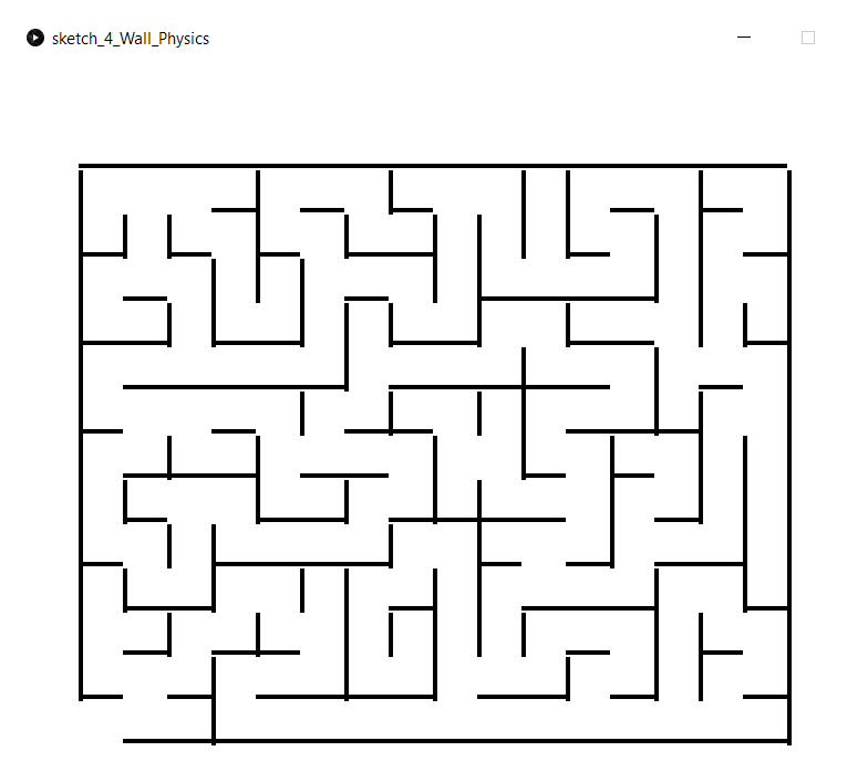
Secondly, I wasn't exactly interested in sketching my own maze, but verifying whether I could replicate some an existing maze using this algorithm. I generated a 17 x 14 rectangular maze using http://www.mazegenerator.net/ and then created a 3-dimensional integer array table containing each coordinate value based on the maze design.
So what does the table look like? It took me around 10 minutes to generate this table by observing the maze generated from the website (which will be shown a couple of images later).
- The first dimension represents the number of columns;
- The second dimension represents the number of rows;
- The third dimension represents the bool pair for generating a horizontal and/or vertical line, as described above. For example, a horizontal line would be denoted by a value of {1, 0}, a vertical line would be denoted by a value of {0, 1}, and both (an "L" shape) would be denoted by {1, 1}.

I modified the loop to factor this in, and compiled the sketch.
{
for (int j = 0; j < rows; j++) //R = 14
{
h = maze[i][j][0] == 1 ? 0.9 : 0;
v = maze[i][j][1] == 1 ? 0.9 : 0;
fboxes[j][i] = createWall(0.1 + h, 0.1 + v, 1.8 + 1 * i, 15.5 - j);
world.add(fboxes[j][i]);
}
}
Of course, sketches never work as intended the first time:
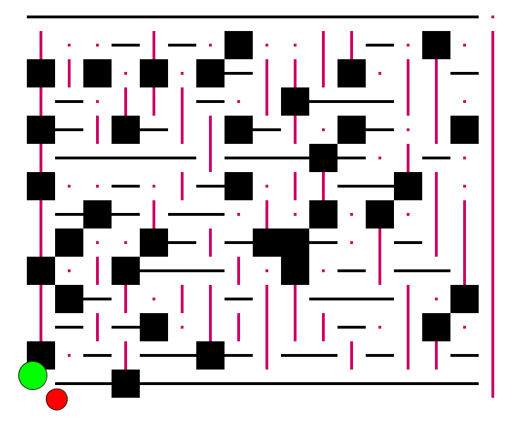
This was disappointing to see even though it resembled a maze of some sort, but I figured out that I had mixed up the row-column order in the table matrix, and then realized that using one FBox for each point yielded a strange problem where an entire "cell" would be covered instead of generating an "L" shape if both a horizontal and vertical line were set for a particular point - you can see this at certain points in the above image. I was unable to figure out why for over an hour, so I decided to use a separate FBox array for the horizontal and vertical lines. This amazingly worked, and I was happy with the results, shown below and juxtaposed with the maze I generated from the website:

This looks almost exactly like the maze I generated from the website! I tweaked a few points, so it is not exactly the same. The only issue now was each "point" providing force-feedback and blocking the player from moving their avatar through the maze path. I figured an easy way around this was to not generate the FBox for a coordinate pair if both the horizontal and vertical bools for each point were set to false, or in other words, had a value of {0, 0}:
Now I could customize the maze by varying the booleans for each coordinate pair. You can tell the initial positioning system I used is slightly off as the lines aren't perfectly aligned, but by an insignificant amount that does not affect the force-feedback effect. It would be interesting to automatically generate the entire table using some image recognition techniques, but that is beyond the scope of this work. However, it is something interesting to consider as it would allow for random mazes to be generated efficiently.
Lastly, I wanted to spice up the maze with an obstacle; what I had done in the past few hours was more maze-algorithm generation work than testing out any additional interaction effects one could utilize with the Fisica library. The most obvious obstacles that came to mind were simple Pacman-style enemies that would move unidirectionally from wall to wall and reset the maze if touched. My idea was to create a standard FBody, such as a circle, give it a nice appearance by attaching an image, and have it move quickly between two opposite walls. I looked up the Fiscia documentation and was amazed by the wide number of dynamic property functions. I initially kept the bodies static and adjusted their positions based on a timer, but the movement was erratic; working with a zero world gravity and setting appropriate bodies' restitution and velocity values based on the documentation info provided smoother results. I tried to be careful not to place the sprites in positions that would give the player hints regarding the maze route, but possibly instead in misleading spots.
The code to generate one of these dynamic bodies is shown below:
{
obj.attachImage(loadImage("../img/ghost.png"));
obj.setPosition(xpos, ypos);
obj.setFill(128, 255, 0);
obj.setStatic(false);
obj.setVelocity(xsp, ysp);
obj.setRestitution(1.0);
obj.setDamping(0.0);
obj.setGrabbable(false);
world.add(obj);
}
As you can see, there is some small code written in the simulation thread that "ends" the maze once the red circle is touched: this wipes out the grid by setting a gameStart flag, and removes all sprites from the screen. The maze can be reactivated by touching the green circle once again using similar logic.
Reflection:
This was a great lab to work on as it expanded my creativity window, and helped me understand the possibilities of what the Fisica library allows to create interesting puzzles, especially when coupled with the Haply. The lab itself took a lot longer than expected, mostly from trial and error when trying to generate a maze, but every part of the debugging process was enjoyable and I'm satisfied with the end results. I had more ideas such as randomly falling rocks as "enemies", or creating difficulty modes, but any additional work would've taken another non-insignificant chunk of time and I need to work on the other labs too. The key takeaway for me was realizing how much is possible with these two libraries alone and the boilerplate code provided from the example sketches. With regards to the Haply, arguably the only frustrating parts of the experience were the manual need to reset the Haply position when restarting the sketch, and myself occasionally forgetting to switch back on the motor adapter (I turn off the motor switch whenever the Haply "randomly" exerts a force without interacting with an object - I think this usually happens from strange effects generated by "faulty" code).
The code can be found here. Note that there is sometimes a random glitch in the code where an exception is raised upon touching a body. I am not sure why this happens, as the error message provides absolutely no useful information ("AssertionError" is all I see on the Processing console) and the glitch occurs randomly. It could be related to the rendering or removing of the dynamic bodies, but I did not want to spend much time on trying to fix the issue since a simple workaround is restarting the sketch.
Thanks for reading, and apologies if this post was longer than it should've been.


Comments
Post a Comment